Combustion Equipment |  |
|
We have designed a range of TES biomass and coal combustion equipment. The equipment can be installed on boilers within the capacity range of 25 to 250 tons/hr:
 |
 |
 |
| Triple Drum Feeders |
Pneumatic Spreaders |
Stokers + Grates |
The pictures above are hot links to descriptions of the equipment.
Some of the best known names in fibrous fuel boilers have used the equipment under licence. The equipment is also available to end users wanting to upgrade their boilers.

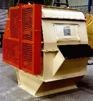
TES Triple Drum Feeders
The controlled feeding of bagasse - and similar biomass fuels having matting properties - without introducing tramp air to the boiler is notoriously difficult. In the case of bagasse, care must also be taken to match the feeders to the physical properties of the fuel: diffuser bagasse is markedly different from milled bagasse.
Tall chutes placed above the feeders are best used to exclude tramp air, the fuel itself providing the seal. With this arrangement the feeders, which meter the fuel into the boiler, have to be able to work when choke fed. Earlier types of feeders such as the horizontal chain type or single drum feeder, cannot do this effectively.
The TES triple drum feeder, the development of which has focused on eliminating chokages and smoothing fuel flow, can operate comfortably with 10 m high chutes. These chutes, in addition to providing the required seal, provide a buffer inventory of fuel to help smooth boiler control.
The two small drums at the top of the feeder meter the fuel. A large toothed drum, running at a much higher peripheral speed, provides a carding action to ensure a steady flow of discrete particles to the spreader.
A facility is incorporated to introduce a second fuel such as coal or wood chips through the feeder to the lower fuel chutes.
The TES feeder incorporates an improved drive train and is offered with a simple electronic speed control that accepts an input signal from the boiler's fuel control loop. Bagasse volumetric flow is essentially linear over the full feeding range. Level probes to provide either a switching or monitoring action can be provided for the inlet chutes.
The feeders are available in three different body sizes to ensure that all boiler configurations can be accommodated. The operating conditions and drive train must be matched by computer to the boiler design duties.
|
By the end of 1998, over 70 units had been supplied for boilers ranging in size from as small as 25 t/hr up to 200 t/hr. Some of the boilers were new installations while other feeders were retro-fitted to older units. The new boilers were either TES units or ones manufactured by one or other of the international boiler companies licensed to use TES feeders in their designs.

TES Pneumatic Spreaders
Biomass fuels such as bagasse have a low density with a high moisture and volatile content. They are therefore best burnt in suspension.
In the past, solid fuel fired boilers used mechanical throwers to spread the fuel into the furnace. However these are not effective with low density fibrous fuels such as bagasse where pneumatic spreading does a better job. The situation becomes more complex when dual firing with bagasse and coal or wood chips is envisaged.
The TES pneumatic spreader is able to distribute both fibrous and granular fuels. These spreaders, which bolt onto the front panel of the furnace, are air cooled.
In order to provide the flexibility needed for dissimilar fuels, the spreaders have two independently controlled air nozzles. The main nozzle propels the fibrous fuel into the furnace while the second, smaller nozzle boosts the air supply when spreading denser fuels like coal or wood chips. The fuels are blown over distribution plates which are individually matched to their furnace location. The "throw" of the fuel into the furnace can be set by adjusting either the angle at which the distribution plates are set or the conveying air pressure.
The spreaders are made of SS 304 except for the deflector plates which, being exposed to direct furnace radiation, are of SS 310.
|
Various boilers, ranging in size from 65 t/hr to 227 t/hr, have been equipped with TES spreaders. Some of them have fired only bagasse while others have fired both bagasse and coal.
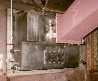
TES Steam Cleaned Pinhole Grates
Low ash content biomass fuels are best burned on stationary steam-jet cleaned grates. These can be either air or water cooled. Both designs simplify cleaning and therefore reduce labour requirements. In addition, they require less maintenance than dump grates.
TES pin-hole grate designs are available in air and water cooled versions. A water cooled version is illustrated below.
The grate bars are supported on an extension of the furnace rear wall tubing; the water flowing through the tubes cools the grate. Combustion air is blown through the support tubes in the air cooled version. In either case the grate can be supplied zoned or unzoned.
The steam-jet nozzles are made of stainless steel. They are placed and directed to sweep the residues down to the front of and then off the grate. The steam supply to the nozzles can be automatically controlled if required.
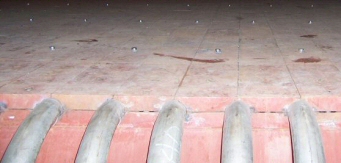
Primary combustion air is supplied through holes in the grate bars. The bottoms of the grate bars are finned to help keep them cool.
The first TES pin-hole grate was installed on the 113 t/h Appleton boiler. It was commissioned in April 2002 and is operating well. Other TES boilers up to 210 t/h have been fitted with this type of grate since then and also operate well.
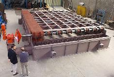
TES Continuous Ash Discharge Spreader Stokers
 Coal fired boilers are often equipped with continuous ash discharge [CAD] spreader stokers. Fibrous fuels are best burned on steam-jet cleaned stationary grates. Air or water cooled vibrating grates can be used to burn fibrous fuels with a high ash content.
On a spreader stoker, coal is thrown largely to the rear of the furnace from where it travels, whilst burning, to the front where its ashes are discharged. As the coal moves forward the amount of air required for combustion varies. The undergrate air supply must therefore be controlled along the stoker length to achieve efficient combustion and reduce harmful environmental emissions. Some form of undergrate zoning to allow variable air distribution is therefore required.
Firing two dissimilar fuels, such as coal and bagasse, in the same furnace requires special consideration. Because a CAD stoker is required to burn the coal, it must also be used to fire the bagasse. However the two fuels require different undergrate air distributions and the ability to control the air distribution becomes essential to achieving efficient combustion.
In addition to the combustion process aspects of CAD stokers, the designer also has to design for longevity in the arduous conditions in which the unit is to operate.
|
 The TES CAD stoker addresses all of these issues and was specifically designed to eliminate many of the drawbacks of existing stokers. The stoker is available fully zoned, partly zoned or without zoning in a modular range of sizes. Air distribution can be controlled either manually or automatically, as required. Zoning can also be retro-fitted if necessary.
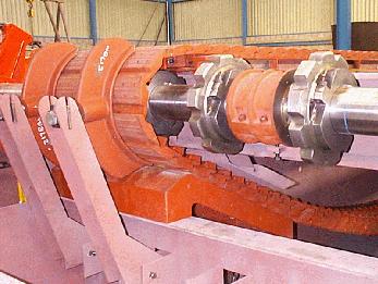
The stoker is robust: for instance, grate bars are only 780 mm long, shafts are 140 mm in diameter and journals are hard chromed for long life.
The stoker structure has been designed to support the boiler pressure parts. Special sidewall and rear wall seals are available which eliminate the need to install refractory at grate level.
Coal reactivity and biomass fuel moisture content are two of the many parameters which are used to select optimum stoker ratings. Bagasse and coal can be burned simultaneously on TES CAD spreader stokers provided that the ash chemistries are compatible.
|
The first TES CAD stoker was delivered for inclusion in a new 100 t/hr Babcock Africa boiler in Southern Africa. The picture above was taken during its test assembly and proving trials in Capetown. All units are trial assembled prior to despatch. The boiler was commissioned in mid 1999 and it, including the stoker, is working well.
|